Connect the controller like a real device
Expose live Modbus values over TCP or RTU so the external application can connect immediately.
ModbusSim is a Windows desktop application that simulates TT and VT compressor behavior over Modbus TCP or RTU. Connect an external controller, run realistic compressor responses built from field logs and engineer-estimated curves, monitor how the control system performs, and export evidence from the session.
Use it for first connection checks, realistic behavior testing, machine log replay, and control-quality review.
A generic Modbus tool can prove that a register map exists. It does not tell you whether an external control system starts, loads, unloads, protects, faults, and resets a compressor system correctly.
Expose live Modbus values over TCP or RTU so the external application can connect immediately.
Use field-log evidence and engineer-estimated curves instead of relying on one narrow formula or one narrow recording.
Monitor transitions, warnings, faults, and recovery, then export the session for review.
The application should feel like an engineering test workflow, not like a register editor.
Set the compressor type, live system layout, and Modbus connection so the external application can talk to the simulator as if it were the target system.
Use field logs where real data exists and complete the missing ranges with engineer-estimated curves where the logs do not cover startup, shutdown, fault, or wider capacity behavior.
Start the external controller and apply the test demand or event. Check how the simulated compressor moves through startup, running, unloading, warning, fault, and reset conditions.
Use the Control Quality Monitor to compare command and response, capture timing and state changes, and export a report when the run should be kept as engineering evidence.
These screens show the main surfaces used during controller connection, behavior setup, monitoring, and report preparation.
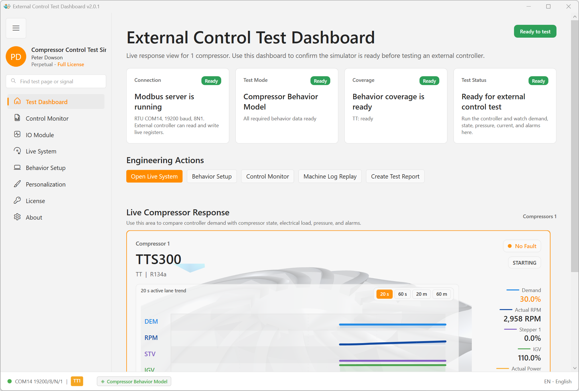
Live compressor state, demand, RPM, pressure, power, and connection status.
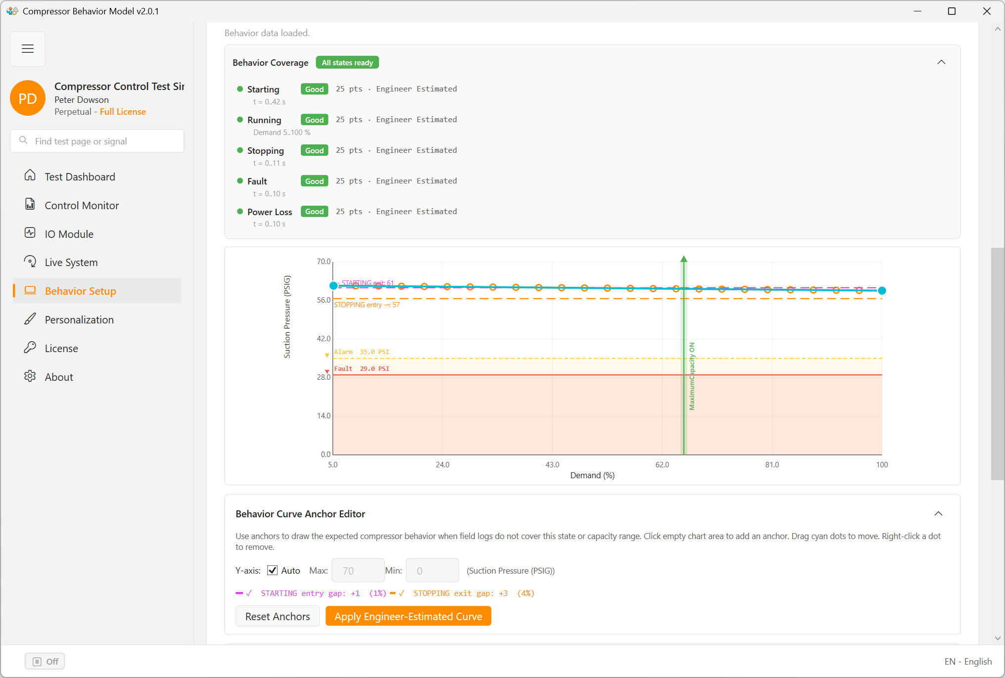
Compressor behavior model setup with editable engineering inputs.
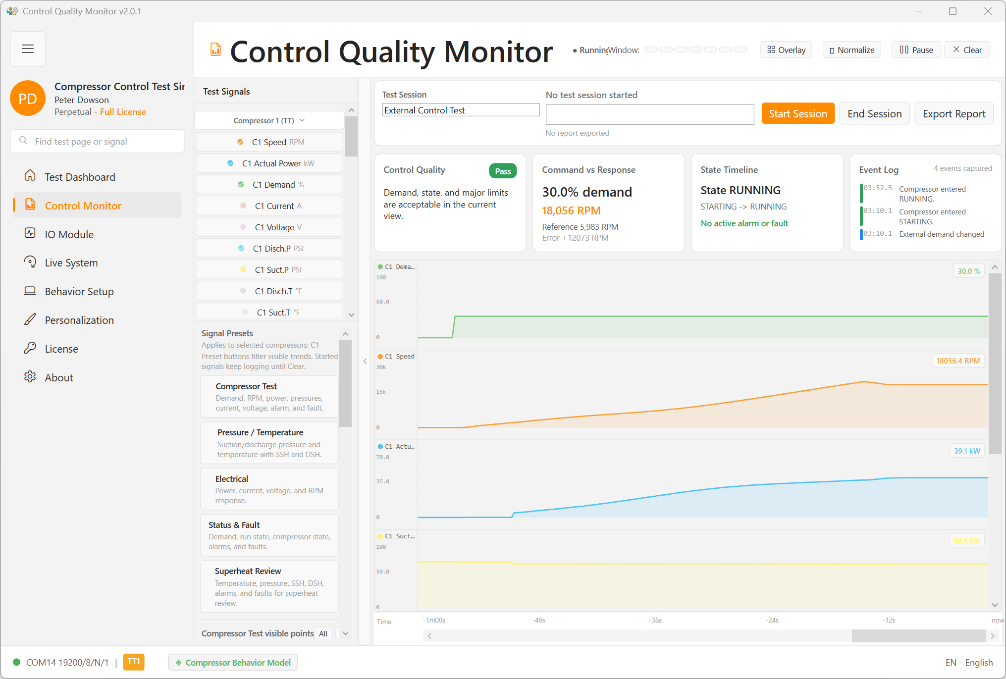
Monitor view for command, response, trends, and report evidence.
The product includes three main user-facing modes because HVAC testing needs more than one kind of realism.
Use this as the main engineering mode. It combines field-log evidence with engineer-estimated completion so the simulated compressor can answer the controller across a wider operating range than a single recorded log.
Replay one recorded machine log exactly. Use it when you want to compare the simulator against a known event, confirm that a captured sequence can be reproduced, or run a regression check against a reference recording.
Use this for first communication checks and coarse troubleshooting when the behavior model is not ready yet. It is useful for getting a controller connected quickly, but it should not be treated as the final realism target.
An off or hold state can also be used when values need to stay fixed, but the three modes above are the main testing paths.
Real projects rarely include complete logs for every startup profile, capacity point, warning threshold, fault event, or power-loss condition. A useful simulator cannot stop where the field log stops.
The behavior model uses real machine data where it exists and lets the engineer complete the uncovered ranges with estimated curves where it does not. That makes the simulator practical for real controller testing instead of limiting it to one narrow replay.
Behavior setup view for combining field-log evidence with engineer-estimated curve completion.
The evidence view of the application. Use it to judge what the controller requested, what the simulated compressor answered, when warnings or faults appeared, and whether recovery happened correctly.
A good report should let another engineer understand what was tested, what conditions were applied, and whether the result was pass, watch, or fail.
Documentation gets the engineer started. Pricing explains the license path. Download and support complete the installation and trial workflow.