Field logs where available. Engineer curves where needed.
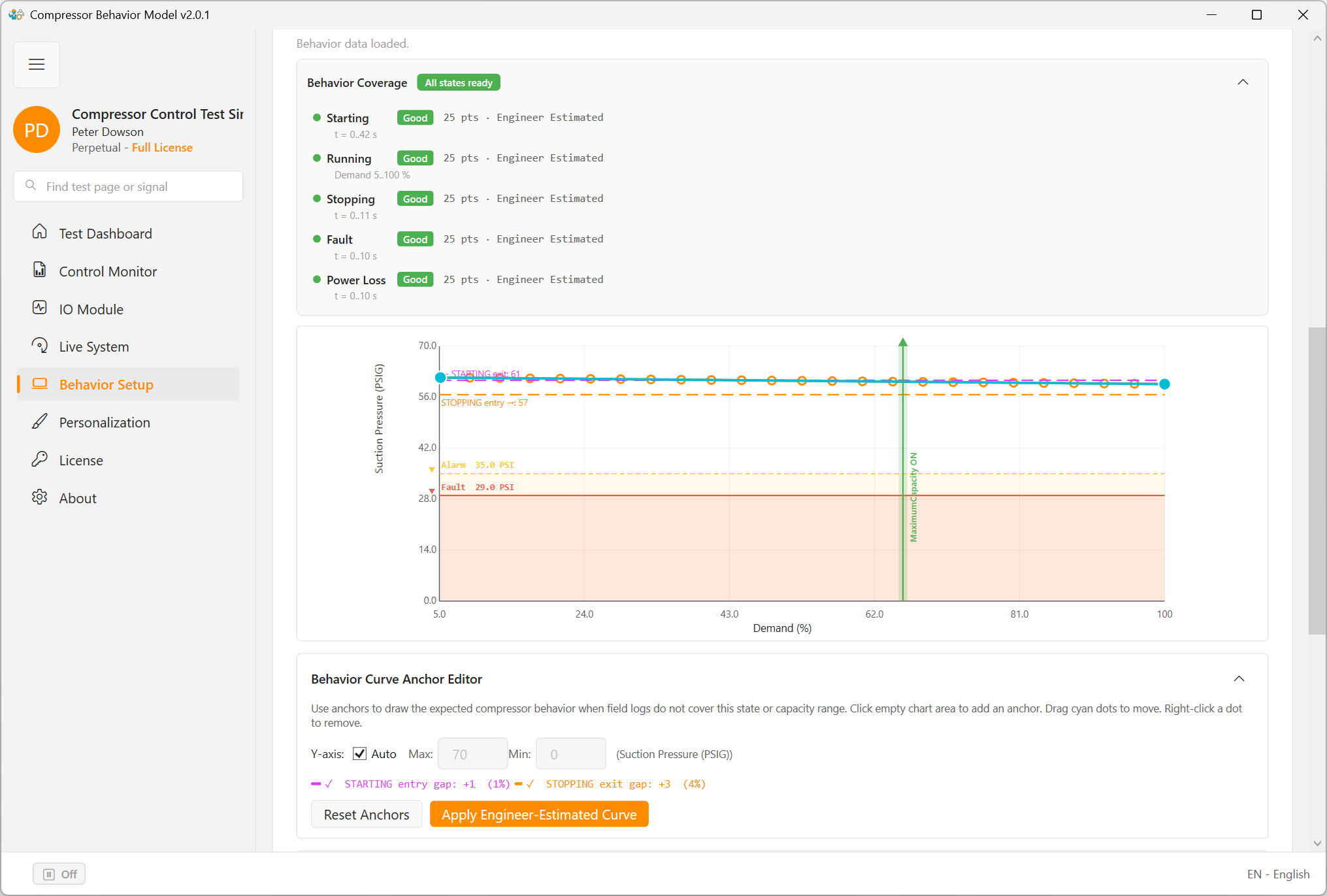
The behavior model is the main engineering surface of the application. It lets an HVAC engineer define how the compressor system should answer an external controller across startup, running, shutdown, warning, fault, and recovery conditions. Before training, use the CSV trend preview to confirm that the prepared log is good behavior evidence.
What realistic means in this product
Realistic does not mean pure math only, and it does not mean replay one real log only. Realistic means the response matches known field behavior where logs exist, missing ranges are completed by engineer-estimated curves where logs do not exist, and the resulting pressures, temperatures, speeds, power, warnings, and fault timing are believable to an HVAC engineer.
The best practical model is usually a combination of field-log evidence and engineer-estimated completion.
Behavior input types
Field log
- Use field logs for startup and shutdown timing.
- Use field logs for running points at known capacities.
- Use field logs for actual pressure and temperature relationships.
- Use field logs for observed warnings and faults when they exist.
Engineer estimated
- Use estimated curves when the machine cannot safely be driven through all capacities.
- Use them when no complete fault or power-loss log exists.
- Use them when startup or shutdown was logged poorly.
- Use them when the available log does not cover the required controller-test range.
Behavior table sources
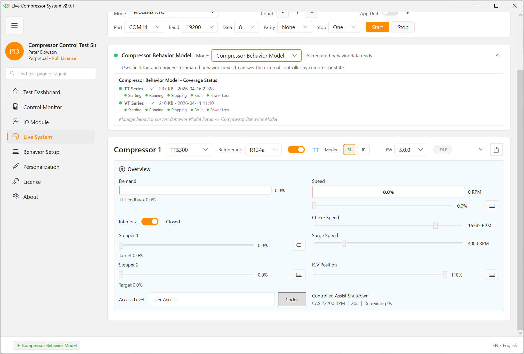
ModbusSim separates model identity, training evidence, and runtime behavior output. A CSV file is evidence used for training. A behavior table JSON file is what the simulator loads during a behavior-model run.
BehaviorModels\TT\TTH375_R513A\behavior-table.json
Exact selected-model table. This is the preferred output from Behavior Curve Editor import and manual tuning.
BehaviorModels\TT\TrainedStateTables_TT.json
Generic TT fallback table. VT uses BehaviorModels\VT\TrainedStateTables_VT.json.
TT_Table.csv, TT_Startup.csv, TT_Shutdown.csv
Selected-model import files. Their suffix controls running, startup, shutdown, or power-loss role.
TT_Global_Table.csv and VT_Global_Table.csv
Global fallback build inputs. Use these only when intentionally rebuilding the family-level fallback table.
model-profile.json
Model identity, limits, register-default notes, and source notes. It is not the trained response table.
When an exact selected-model behavior-table.json exists, the editor and runtime should use it first. If it does not exist, the system can use the TT or VT fallback table under BehaviorModels.
Machine Log Replay is separate from this flow. Replay feeds one recorded event back through the simulator. The Compressor Behavior Model uses trained and edited behavior tables so the controller can move across a wider operating range.
Recommended mode priority
- Compressor Behavior Model
- Machine Log Replay
- Basic Calculated Model
The behavior model supports realistic testing over a wider engineering range. Replay mode is exact but narrow. Calculated mode is useful but incomplete.
Practical modeling workflow
- Confirm the active compressor family, model, refrigerant, and lift mode.
- Choose the selected-model import workflow unless you intentionally need a generic TT or VT fallback build.
- Prepare role-specific CSV files for running, startup, shutdown, and optional power-loss behavior.
- Open the CSV trend preview before import and reject files with poor trend quality.
- Import the accepted CSV files into the selected model and confirm the save target is the expected
behavior-table.json. - Check startup, running, and stopping coverage first.
- Review suction pressure, discharge pressure, suction temperature, discharge temperature, suction superheat, discharge superheat, speed, power, current, and controller-visible status values.
- Add engineer-estimated points where the logs do not cover the required range.
- Run the external control application, observe the result in the monitor, export a report, and adjust only where the result was not believable.
CSV trend preview before training
The Open CSV tool opens the Open Trend of Selected CSV window for the selected behavior source. Use it as a visual quality gate before training or importing a log. The table preview shows row count, trend columns, compressor number, and the chart X axis, commonly demand percent for a running table.
Accept the CSV when
- RPM, power, pressure, temperature, and superheat trends are smooth and readable against demand.
- The demand range covers the controller test you need.
- The selected rows represent the intended state, such as running for
TT_Table.csvorVT_Table.csv. - The chart does not include staging transitions, idle sections, fault sections, or unrelated compressor activity.
Reject or replace the CSV when
- The trends show repeated vertical bands, jumps, heavy oscillation, or broken relationships versus demand.
- The table contains mixed states that do not match the file role.
- The updated loader can remove repeated points, but the remaining trend still does not describe believable compressor behavior.
- A better source log is needed from the service technician before training should continue.
Use Save PDF from the preview when another engineer or service technician needs to review why one CSV was accepted and another CSV was rejected.
What to tune first
TT and VT startup
- Time to spin
- RPM rise shape
- Power rise
- Pressure movement and transition into running
Running and protection
- Low, medium, and high demand response
- Stable pressure and temperature trends
- Believable power and current
- Warning before fault and correct reset path
Acceptance checklist
- The engineer understands which states are covered.
- The expected operating range is visible.
- The selected-model behavior-table path or fallback source is understood.
- The prepared CSV files passed visual trend review before import.
- The key limits are visible.
- The controller can be tested without relying on guesswork during the run.